
Embedded Systems · 3 min read
Designing Reliable Sensor Signal-Conditioning Circuits
The quality of a measurement is decided in the first few centimetres of copper after the sensor. Here is how to get them right.
NANOSOFT Engineering Insights
Understand the sensor first
Output type, source impedance, signal range, bandwidth and excitation needs define the front-end. A thermocouple, a strain gauge bridge and a 4–20 mA transmitter call for very different circuits.
Amplification
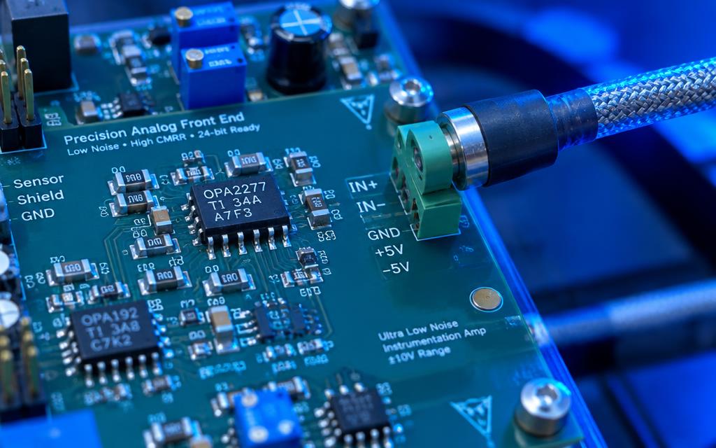
Gain should bring the signal close to the ADC full-scale range without clipping under worst-case conditions. Instrumentation amplifiers are preferred for differential and bridge sensors because of their common-mode rejection.
Filtering
An anti-aliasing filter limits bandwidth before sampling. Its corner frequency follows from the required signal bandwidth and the sampling rate. Digital filtering in firmware can then refine the result.
Protection without compromise
Every protection element adds leakage, capacitance or noise. Choose and place them so that they protect without dominating the error budget.
- Series resistance and clamp diodes for over-voltage
- Low-leakage TVS devices on exposed lines
- Reverse-polarity protection on sensor supplies
References and grounding
A measurement is only as good as its reference. Use a stable voltage reference, consider ratiometric measurement where possible, and keep analog return currents away from noisy digital paths.
Frequently asked questions
Working on something similar?
Tell us about your application and we'll respond with practical engineering next steps.
Have a custom electronics project in mind?
Share your requirements and get a structured engineering response from our team.