
Product
Electromagnetic Flowmeter Circuit
Purpose-built circuit engineering for magnetic flowmeters: stable coil drive, low-noise electrode front-ends and dependable outputs your instrument can build on.
Technical overview
How it works.
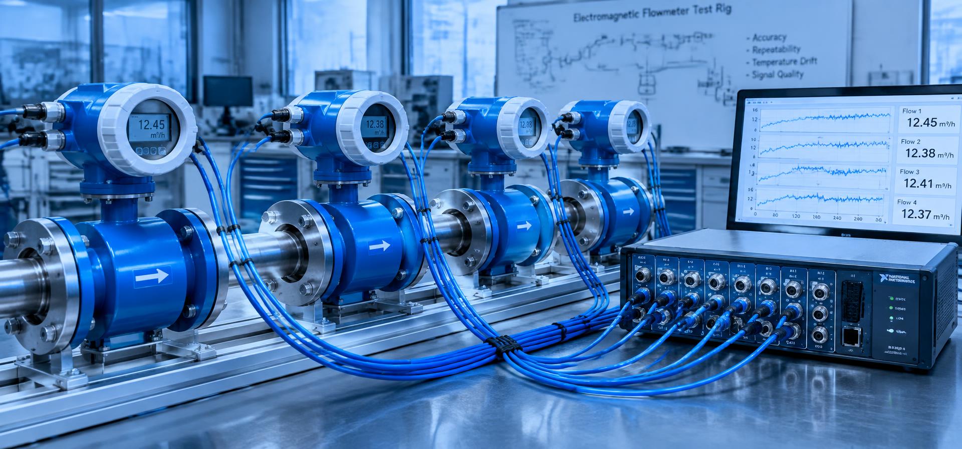
An electromagnetic (magnetic) flowmeter measures the velocity of a conductive liquid by applying Faraday's law of induction. A magnetic field is generated across the flow tube, and the moving liquid induces a small voltage between two electrodes. That voltage is proportional to the average flow velocity and, with a known pipe diameter, to the volumetric flow rate.
The electronics are what make that principle usable. The induced signal is typically in the microvolt-to-millivolt range and sits on top of electrochemical offsets, common-mode interference and noise. NANOSOFT develops flowmeter circuit boards that address excitation, signal acquisition, processing and output as one coherent system, tailored to the sensor and application you are building.
Coil excitation
Controlled, typically pulsed-DC or low-frequency alternating coil current to create a stable magnetic field while avoiding the polarisation effects of steady DC.
Electrode front-end
High-impedance, high-CMRR differential acquisition designed around electrode characteristics, cable length and the liquid's conductivity range.
Synchronous processing
Sampling aligned with the excitation phase so that settled signal windows are measured and offset drift is rejected.
Outputs & interfaces
Analog current loop, pulse/frequency outputs, digital communication and local display options as required by the instrument.
Simplified for illustration. Actual architecture is defined per project.
Applications
- Water supply and distribution metering
- Wastewater and effluent monitoring
- Process liquids in industrial plants
- Irrigation and agricultural flow systems
- OEM instruments requiring an embedded flow board
- Retrofit electronics for existing flow tubes
Customisation
- Pipe size range and coil characteristics of your sensor
- Excitation frequency and current profile
- Expected liquid conductivity and electrode material
- Power source: mains, loop-powered or battery operation
- Output types, communication protocol and display
- Enclosure size, connectors and environmental conditions
Integration
- Board form factor designed around your enclosure and mounting
- Calibration hooks and parameter storage for factory setup
- Firmware structure for zero, span and damping configuration
- Diagnostics such as empty-pipe detection and coil fault indication where required
FAQ
Electromagnetic Flowmeter Circuit questions
Inquiry
Discuss your requirements.
Tell us about your sensor or transducers, power, interfaces and quantities. Attach drawings privately if helpful.
Have a custom electronics project in mind?
Share your requirements and get a structured engineering response from our team.