
Flow Measurement · 3 min read
Electromagnetic Flowmeter Circuit: Working Principles and Design Considerations
From Faraday's law to a stable reading: the building blocks of magnetic flowmeter electronics and the decisions that shape them.
NANOSOFT Engineering Insights
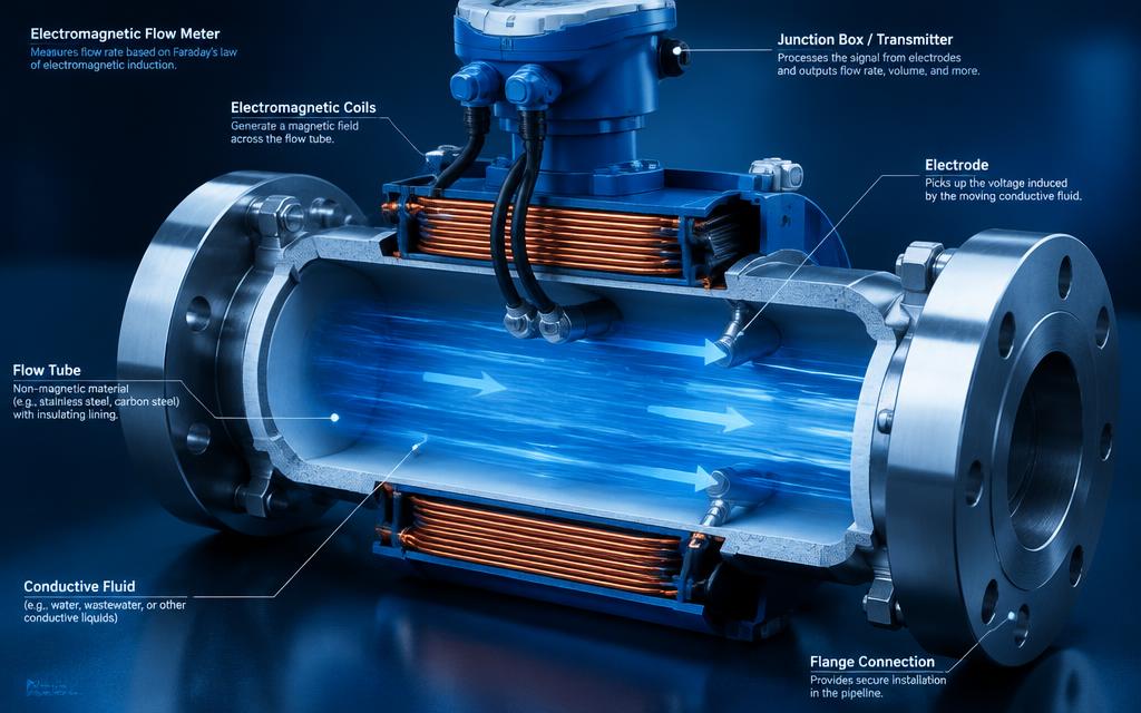
The principle in one sentence
A conductive liquid moving through a magnetic field induces a voltage perpendicular to both the field and the direction of flow. Two electrodes in the pipe wall pick up that voltage, which is proportional to the average flow velocity.
Simple as that sounds, the induced signal is small — often in the microvolt to low-millivolt range — and it sits on top of much larger disturbances. The electronics exist to extract that signal reliably.
Coil excitation
Most designs avoid steady DC excitation because it polarises the electrodes and causes drift. Instead, the coil is driven with a pulsed or alternating current at a low frequency. Each half-cycle produces a field of opposite polarity, and the difference between the two settled readings cancels many offsets.
Current control
A regulated coil current keeps the magnetic field consistent over temperature and supply variation. Field stability translates directly into measurement stability.
Frequency choice
Lower frequencies give more settling time and less eddy-current influence; higher frequencies respond faster and reject slurry noise better. The right choice depends on the sensor and the liquid.
Electrode signal conditioning
The front-end must present a very high input impedance, because electrode source impedance varies with liquid conductivity. It must also reject large common-mode voltages.
- Differential instrumentation amplifier with high CMRR
- Input protection that does not add leakage or noise
- Guarding or driven-shield techniques for long cables
- Filtering matched to the excitation frequency
Synchronous sampling and processing
The microcontroller samples the conditioned signal in windows aligned with the excitation phase, after the field has settled. Averaging across many cycles, combined with damping filters, produces a stable flow reading.
Firmware also handles zero and span calibration, unit conversion, totalisation and diagnostics such as empty-pipe detection.
Key design considerations
Considering these together, early, avoids the most common source of disappointment in flowmeter electronics: a well-designed circuit that does not suit the sensor it is paired with.
- Sensor coil inductance and resistance
- Range of liquid conductivity expected in service
- Cable length between sensor and transmitter
- Power budget and supply type
- Required outputs and update rate
Frequently asked questions
Working on something similar?
Tell us about your application and we'll respond with practical engineering next steps.
Have a custom electronics project in mind?
Share your requirements and get a structured engineering response from our team.